It took me a fair while to get my 450 airborne with not knowing anything about the hobby and did a lot of research. The whole process wasn’t listed anywhere with the items I used, so thought I’d write a buildlog of my process, perhaps it would help someone else.
Here is my build list of parts:
- DJI F450 Flamewheel ARF kit
- This includes the Naza V2 GPS, flamewheel kit, landing legs, E300 ESC’s 9200KV motors and DJI props (4 x cw (counter clockwise) and 4 x ccw (counter-clockwise), battery strap, Velcro, screws and odds and sods.
- Turnigy 9X transmitter Mode 2 and 8 channel receiver
- 2 x 3s 2200mAh batteries
- XT60 connectors, both male and female (spares, not req in this build)
- B6 Imax Smart charger
- Lipo-Safe bag (Lipo’s known to explode on charging and storage, this attempts to control the fire)
Things you need to build this kit:
- Decent soldering iron, suggest at least a 40w, I use a 30W/60W switchable soldering iron, very handy!
- Solder, I use non lead fluxed solder, I cba to use separate flux (lots of people will bitch at me for that)
- Heatshrink tubing, 5mm is handy size
- Third hand tool
- Wire cutters or decent pliers
- Velcro, both sides, peel and stick stuff
- Multimeter (unless your mega confident)
- Hot Melt gluegun or paintable electrical tape
- Pc/Mac for programming
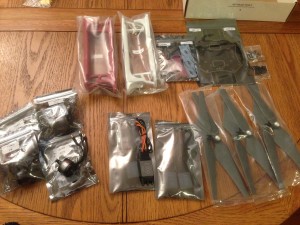
The flamewheel kit:
So lets get started, unpack all the DJI gear and start soldering the base plate, start with the XT60 connector, Female XT60 connector.
A quick lesson on soldering, touch the iron to the pads on the power distribution board (PDB) and then touch the solder to the pad too so the solder melts over the pad and not the iron. Then do the same with each wire, trim half a CM of insulation from the wire, hold it in the third hand tool grip to save your fingers, heat the wire with the iron, touch it with the solder so the solder flows over the wires and binds them together into one mass. This method is known as tinning and is the basis of soldering. When both parts are tinned, touch the iron back to the pad to remelt the solder and touch the wire to the pad, the solder on the wire and the pad should melt together and form a nice fluid join. If they are look like they haven’t contacted decently you may get a cold joint, which won’t pass current effectively, try again. On larger joints I suggest the stronger power iron, it makes life a lot easier, but never touch an iron to a PCB for too long lest you damage any components or compromise the board’s integrity.

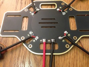
Red wire to the +, black wire to the – pads. Don’t forget to slide heatshrink sleaving over the large 12AWG cable before you then solder the XT60 connector. Grip the XT60 connector in the third hand tool, pay attention to the side as it has a + and – indicating which to solder to which wire. Tin the xt60 connector, and the wires, and join. Then slide the heatshrink over the exposed solder and using either the side of the iron, a heatgun or your mothers hairdryer shrink the tubing to protect it. You must also solder the Naza PMU unit directly to the same pads (notice how i didn’t do it here, and learned later so had to resolder)!
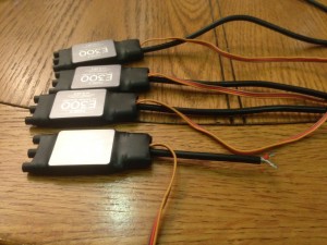
Trim the ESC main wire so you have two wires exposed, tin each wire, and solder to the board each esc.
I used a hot melt gluegun to cover these exposed soldered joins from moisture, you could use liquid/paintable electrical tape.
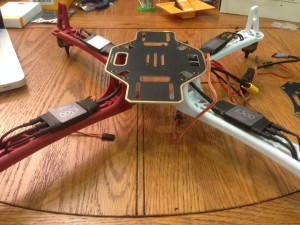
Start bolting the legs to the base plate PDB, I used the configuration of red feet forward, white rear, and the base so there is a lip at the front and rear, rather than at the sides like in the DJI video, otherwise you lose space on the craft.
Something that I learned that I didn’t do here is to pay attention to motor direction. Look closely on the side of each motor, it has a direction arrow, refer to step 2 of the DJI pdf which shows which corner which motor should be put on.
Believe me, I was more than pissed off that I had built a quad and all it wanted to do was flip over on throttle up. The reason this is important was that I didn’t realize DJI uses both clockwise and counter-clockwise thread on the props/motors so they specifically have a corner. Plug the three motor plugs into the esc’s, doesn’t matter which is which right now and cabletie the esc’s to the arms. Many people put them on the top of the arms, I put them underneath and also used extra heatshrink to cover the bullet connectors between the motor and esc join as didn’t find them fitting flush.
Do not fit props, still a lot to do, props are dangerous as hell.
Leave the top plate for now, you need to start looking at the Naza gear.
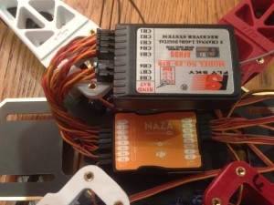
The receiver is supplied power by the Naza flight controller, which in turn is powered from the ESC’s. I jumped in and bought a Turnigy 9x second hand, as wanted a cheap transmitter without really knowing the bigger picture of failsafes, so I’ll include how to wire it up to a 8channel basic Turnigy receiver.
Plug in the receiver to the flight controller as:
- Receiver Channel / Naza V2 Input
- Channel 1 / A
- Channel 2 / E
- Channel 3 / T
- Channel 4 / R
- Channel 5 – Not connected, leave empty
- Channel 6 / U
- Channel 7 / X2
Looks like this:
Now mount this in your quad, note the direction arrow on top of the Naza FC unit, make sure the arrow is pointing directly forward of the quad, and make sure that the FC is in the direct center of the quad. Things start to get tight:
You can see that I’ve connected up all the servo leads from the ESC, that’s pretty straightforward, just follow the PDF from Naza.
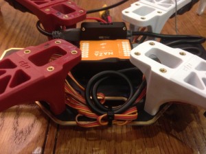
Start plugging the extra components in, I mounted the receiver on the rear tab of the quad, and the PMU to the side of the FC using double sided tape. Carefully bound the servo leads and used a cable tie to secure them:
Here is the LED unit mounted to the side of an arm, with the USB connector available to access. I’ve also plugged the GPS unit into the FC, so for all intents and purposes the quad should be able to be connected to a battery and programmed. Double check all your power connections at this point, make sure everything is as it should be, double check the direction of the motors on the correct arms.
Final view from above before the top plate is attached and screwed down:
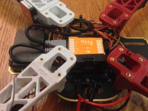
Attach the top plate, cable tie down the ESC’s and attach the battery strap. I would also attach some velcro to the top plate where the battery sits, then the other part of the velcro on the battery itself. This along with the battery strap completely prevents the battery from moving.
Note in this picture the red receiver aerial under the ESC cable tie, this isn’t a good idea as the frame naturally hides the receiver from picking up radio from your transmitter. Things you learn whilst with this hobby. I would later attach it on the lower side of the base plate towards the rear of the quad, giving me better coverage.
So the mechanics is basically done, it’s time to setup the electronics.
Transmitter first, see my posts about switch errors and calibrating the sticks before going any further.
Now follow the steps laid out by the FlyingDutchman on the RumbleCloudRC forum. I followed it to the T and it’s 100% complete. If I were to write out the steps further I would simply copy his!

